العربية
 Español
 Pусский
 lingua italiana
 Français
 Deutsch
 Portugues



Discover how surge protection in outdoor LED drivers improves lighting system reliability. Explore design strategies, failure modes, and test standards for defending against lightning-induced surges.
Outdoor LED lighting, especially street lighting, has grown significantly in recent years. To ensure durability and safety, LED drivers used in outdoor environments must offer high surge protection levels. This article explores surge coupling paths, failure modes in LED drivers, and protective circuit designs that significantly enhance surge immunity and improve the reliability of outdoor LED lighting systems.
1. Types of Surge Voltages Affecting Outdoor LED Drivers
Outdoor LED drivers must withstand various transient voltages, including:
-
Direct lightning strikes: Carry extremely high energy, with peak voltages reaching up to 5,000 kV.
-
Conducted surges: Induced by lightning strikes on power or communication lines.
-
Switching transients: Generated by sudden connection/disconnection of inductive or capacitive loads, often exceeding several times the rated voltage of the grid.
Surge protection in LED drivers mainly addresses conducted lightning and switching surges.
2. Testing Standards for Surge Immunity
Surge testing for outdoor LED drivers follows international standards:
-
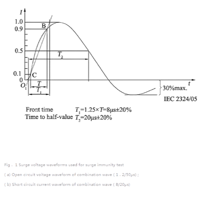
IEC 61643-11: Defines the combined surge waveform (1.2/50μs voltage and 8/20μs current).
-
ANSI C82.77: Specifies a minimum surge immunity of 6 kV/3 kA (differential and common mode) for outdoor luminaires.
The required protection level for outdoor LED power supplies is at least 6 kV differential and common mode.
3. Surge Protection Architecture in LED Street Lights
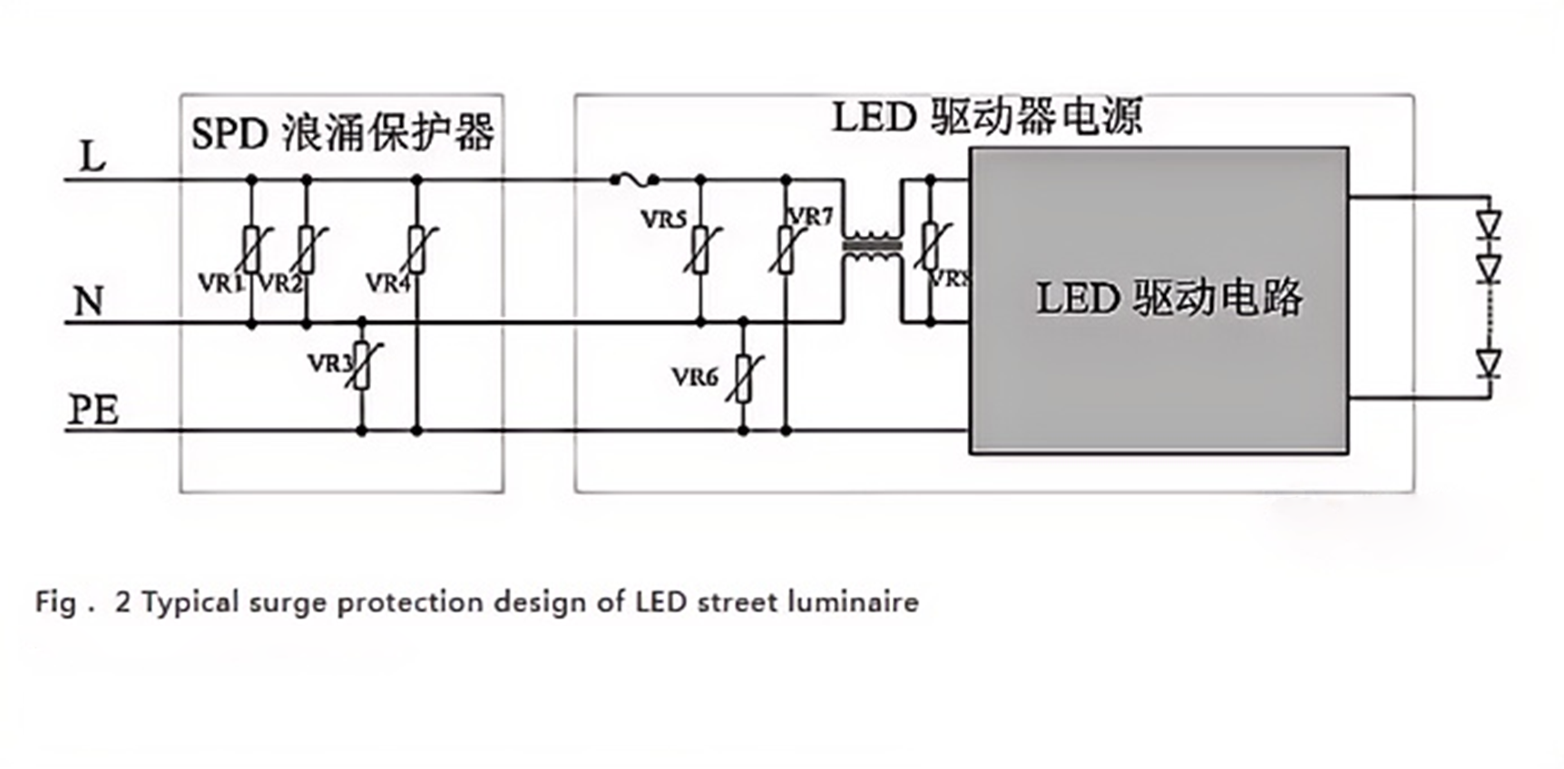
A typical surge protection system includes two stages:
-
Stage 1: External SPD (Surge Protection Device) – Clamps high-voltage surges (10–30 kV) down to 4–8 kV.
-
Stage 2: Internal protection circuit – Further clamps the voltage to below several hundred volts to protect internal circuits.
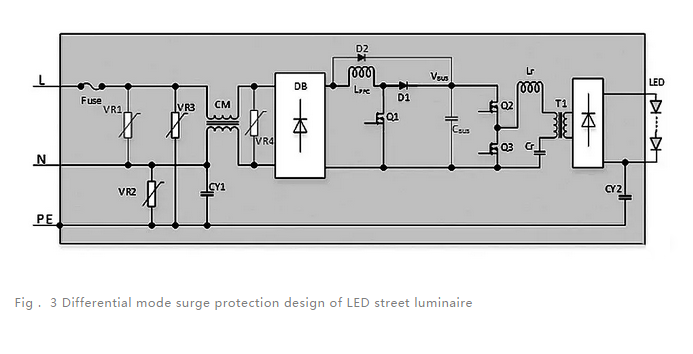
4. Differential Mode Surge Protection Design
Differential surges occur between Line (L) and Neutral (N), or between VBUS and power ground. Common failure modes include:
-
Fuse blown
-
MOV (Metal Oxide Varistor) failure
-
MOSFET or diode breakdown
-
Electrolytic capacitor leakage
Key Design Considerations:
-
Circuit Topology: Boost topology is preferred for the first stage due to its capacitor buffering capability.
-
Clamping Circuit Design:
-
Primary protection uses MOVs rated for 320 VAC and 14 mm diameter to clamp 6 kV surges.
-
Secondary protection uses smaller MOVs and/or TVS diodes to further reduce voltage.
-
-
Smart Switch Protection: Use of controlled switches (e.g., MOSFETs, SCRs) can dynamically isolate clamping circuits, allowing lower voltage MOVs for better protection.
-
Dedicated Protection Circuits: For vulnerable components (e.g., Q1 switch), circuits may actively shut down switching during surge events.
5. Common Mode Surge Protection Design
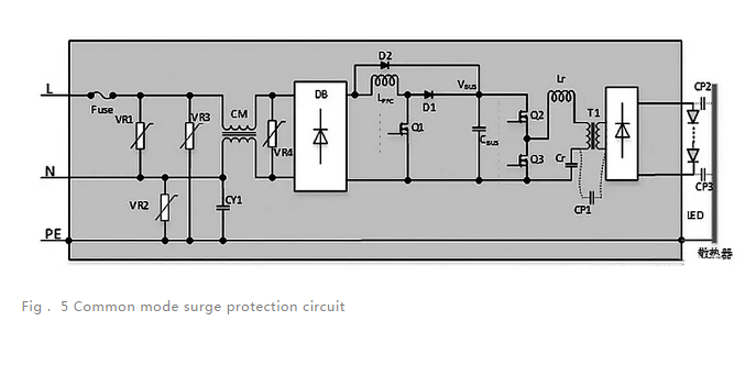
Common mode surges couple between L-PE, N-PE, or both. They mainly affect:
-
LED modules and heat sinks, which form parasitic capacitances with grounding (CP2, CP3).
Design Measures:
-
Use isolation transformers with high insulation and sufficient creepage distance.
-
Minimize capacitive coupling (e.g., CP1) across transformers.
-
Add MOVs or gas discharge tubes at the input stage for common mode clamping.
6. Testing and Results
Test configuration:
-
Surge type: 6 kV/3 kA, 2 Ω impedance, 40 pulses in 4 coupling modes (L-N, L-PE, N-PE, L/N-PE)
-
Stage 1 MOV: 14 mm, 320 VAC
-
Stage 2 MOV: 10 mm, 240 VAC + bidirectional thyristor
The LED driver passed all surge tests. Voltage was effectively clamped:
-
From 6 kV down to 1045 V after stage 1
-
Further down to 620 V after stage 2 — within safe limits for 600 V MOSFETs
7. Conclusion
This study highlights how surge events impact outdoor LED drivers and outlines robust protection strategies for differential and common mode surges. Through proper selection of components, topology, and multi-stage protection circuits, LED drivers can achieve reliable lightning surge resistance, greatly enhancing the longevity and stability of outdoor lighting systems.