العربية
 Español
 Pусский
 lingua italiana
 Français
 Deutsch
 Portugues



Stop paying for grid failures. Learn how the ASL23 uses Class II insulation and Blackbox data-logging to lock your liability boundaries in erratic municipal grids.
How to Lock Liability Boundaries for Early LED Failure Under Erratic Grounding Impedance
1. The Grounding Impedance Problem in Municipal Retrofits
In aging urban grids and regions with high soil resistivity fluctuations, grounding impedance is not static. It shifts seasonally, degrades with pipe corrosion, and varies across a city depending on soil moisture, infrastructure age, and maintenance history.
IEC 60364 (Electrical Installations of Buildings) and local wiring regulations require grounding resistance below defined thresholds — typically below 10Ω for general installations and below 4Ω for lightning protection systems. In practice, municipal infrastructure often exceeds these limits without regular testing.
What Happens When Grounding Drifts
| Grounding Condition | Electrical Effect | Impact on LED Luminaire | Liability Consequence |
|---|---|---|---|
| Normal (< 4Ω) | Fault current drains safely to earth | SPD and driver operate within design parameters | None — system works as designed |
| Degraded (10–50Ω) | Reduced fault clearing speed; PE potential rise | SPD may not clamp effectively; leakage paths form | Premature failures begin; root cause is ambiguous |
| Failed (> 50Ω or open) | No effective earth reference; housing energized | Surge energy has no path to earth; driver destruction | Mass failures; municipality blames "product quality" |
| Intermittent (fluctuating) | Voltage transients, neutral-earth voltage rise | Cumulative stress on MOVs and driver capacitors | Random early failures; impossible to diagnose without logging |
2. How Liability Cascades to the Contractor
In EPC contracts for municipal lighting, the contractor typically carries a performance warranty period (2–5 years) backed by a bank guarantee or retention bond. When luminaires fail prematurely, the following cascade occurs:
↓
Municipality Reports "Defective Product" → Contractor Liable Under Warranty
↓
Replacement + Re-installation at Contractor Cost → Bank Guarantee Drawdown
↓
Liquidated Damages Triggered → Project Profit Eliminated
Why Traditional Approaches Fail
| Traditional Approach | Why It Doesn't Protect the Contractor |
|---|---|
| Higher-rated SPD (e.g., 10kV or 20kV) | SPD effectiveness depends on grounding path. If earth impedance is high, the SPD cannot clamp to a low enough level regardless of its rating. |
| Extended product warranty | Manufacturer warranty typically excludes "external electrical causes." With no evidence of grid abuse, the claim is denied. |
| Contractual force majeure | Grounding degradation is gradual, not sudden. Rarely qualifies as force majeure. The contractor still bears the burden of proof. |
3. Class II Insulation: Eliminating Grounding Dependency
IEC 61140 defines protection classes for electrical equipment. Class I equipment relies on a protective earth (PE) connection. Class II equipment achieves safety through double or reinforced insulation alone — no connection to PE is required.
Class I Luminaire
- Safety depends on PE integrity
- Housing potential follows earth impedance
- SPD clamping degrades with poor earth
- Leakage current find paths through corrosion
Class II Luminaire
- Safety achieved by insulation alone
- Housing physically isolated from live conductors
- Internal SPD clamps L-N without earth dependency
- Leakage paths physically eliminated by design
4. Dual-Redundancy SPD and Diagnostic Logging
Even with Class II isolation, LED drivers remain vulnerable to differential-mode surges (line-to-neutral transients). A dual-stage surge protection approach (10kV + 10kV) provides documented protection per IEC 61643-11.
Diagnostic Data as Legal Evidence
| Diagnostic Parameter | What It Records | Evidentiary Value |
|---|---|---|
| Surge event counter | Number of SPD clamping events | Quantifies external electrical stress exposure |
| Input voltage extremes | Min/max voltage recorded | Proves whether supply was within spec or anomalous |
| Over-temperature events | Times driver exceeded thermal threshold | Distinguishes thermal abuse from normal operation |
5. Photometric Compliance Lock: Preventing Site Rejection
Beyond electrical failures, site rejection due to non-compliant light distribution is a major liability. Three design features work together to eliminate photometric disputes:
- Tool-Free Adjustable Bracket: Positive locking at each position ensuring precise tilt matching.
- Rigid IES-Locked Lens System: Lenses mechanically indexed to fixed positions.
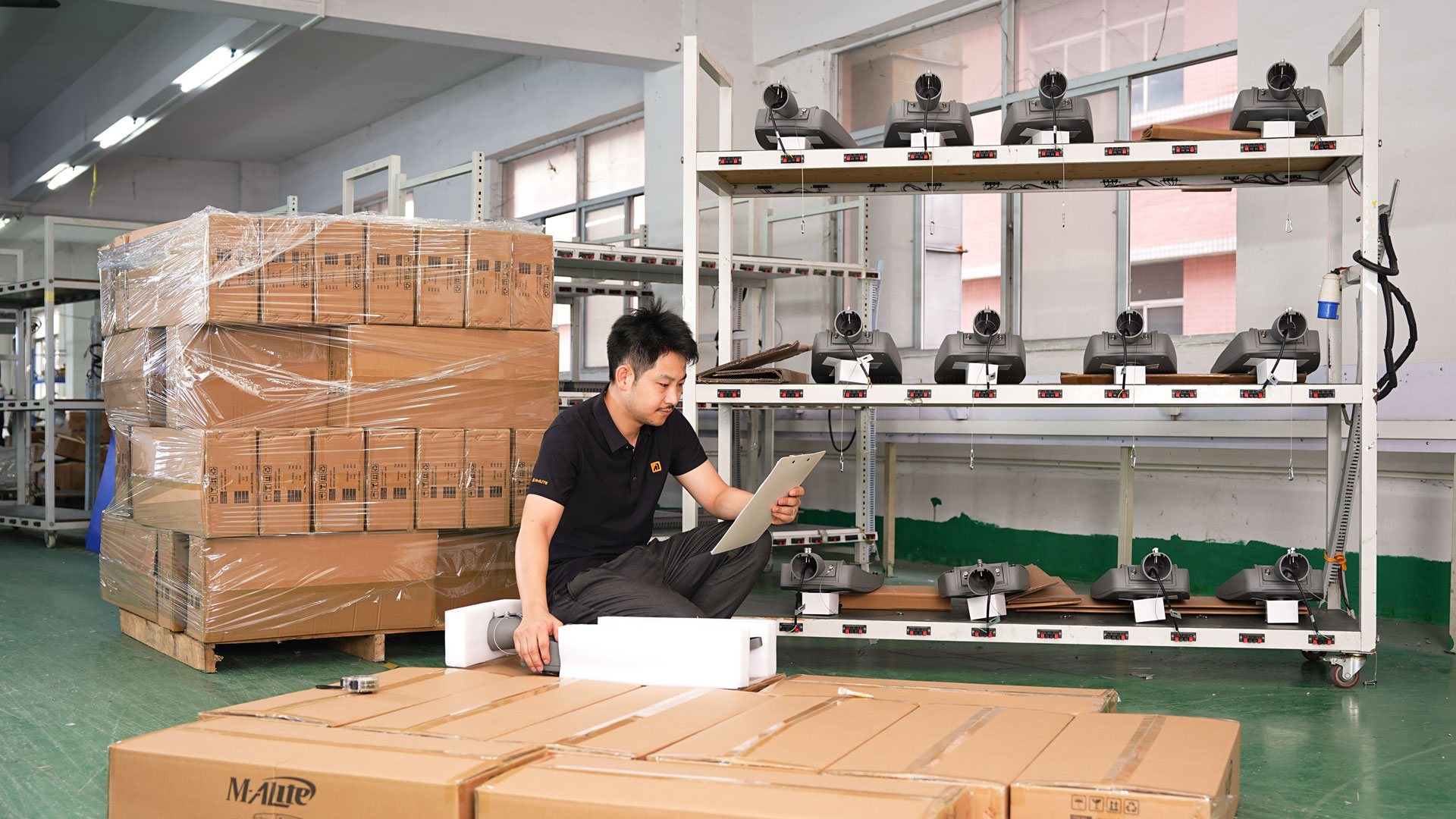
- Pre-Shipping MES Validation: Factory records confirm each unit's lens type and tilt setting.
6. Building a Complete Evidence Framework
Design Phase
Specify Class II luminaire per IEC 61140. Document photometric design with approved IES files.
Manufacturing Phase
MES system records driver model, SPD rating, and photometric batch for each serial number.
Failure Event
Retrieve diagnostic data via NFC before replacement. Correlate failure with logged grid anomalies.
7. Key Specifications for Risk-Aware Procurement
8. Class I vs. Class II: Liability Exposure Comparison
| Scenario | Class I Luminaire | Class II Luminaire |
|---|---|---|
| Grounding degrades >50Ω | Housing energized; safety compromised | No effect; grounding not required |
| Surge event @ poor grounding | SPD ineffective; driver destroyed | Internal SPD clamps; no earth dependency |
| "Product Defect" Claim | Contractor bears burden of grounding proof | Grounding condition is irrelevant to protection |